


All Products
-
 Jake MillerWe took a chance on inverters-vfd.com for a critical VFD replacement on our assembly line. The product was not only a perfect match but also more affordable than our previous supplier. Its stability has eliminated our frequent tripping issues. An outstanding value and a reliable partner for industrial components.
 -
Sarah ChenThe technical team at inverters-vfd.com was invaluable. I described our application for a servo motor, and they recommended a model with superior dynamic response. Installation was seamless, and the precision has improved our cycle times. Expert guidance and a high-performance product!
-
David "Big D" KowalskiOur order for multiple PLC units and HMIs was fulfilled accurately and shipped with astonishing speed. Since integrating them, our control system's communication is more robust. We're impressed by the logistics and the solid performance of these components. A hassle-free experience all around.
-
Emily WhiteWe required a low-noise spindle motor for a sensitive testing environment. The unit we purchased operates whisper-quiet and maintains consistent torque. The quality exceeds some big-name brands we've used, at a fraction of the cost. Exceptional for specialized applications.
VFD Vector Frequency Inverter Variable Frequency Converter For Asynchronous Motor Drive Control


| Place of Origin | China |
|---|---|
| Brand Name | COENG |
| Certification | CE |
| Model Number | HV350 |
| Minimum Order Quantity | 1 |
| Packaging Details | Carton, plywood case |
| Delivery Time | 10-30 working day |
| Payment Terms | L/C, T/T, Western Union |
| Supply Ability | 20000sets/year |

Contact me for free samples and coupons.
WhatsApp:0086 18588475571
Wechat: 0086 18588475571
Skype: sales10@aixton.com
If you have any concern, we provide 24-hour online help.
xProduct Details
| Input Voltage | Input Voltage: 380V (-15%) To 480V (+10%) Phase: Three-phase | Input Power Frequency | 50Hz/60Hz ±5% |
|---|---|---|---|
| Output Voltage | 0V~Input Voltage | Output Frequency | 0~600Hz |
| Master Control Motor Type | Asynchronous Motor | Master Control Speed Range | 1:10 V/F;1:100 OLVC;1:1000 CLVC |
| Master Control Mode | V/F, OLVC(Open-loop Vector Control), CLVC(Closed-loop Vector Control) | ||
| Highlight | Asynchronous Motor Drive Control VFD,Variable Frequency Converter VFD,Vector Frequency Inverter VFD |
||
Product Description
HV350 General Purpose VFD Vector Frequency Inverter Variable Frequency Converter For Asynchronous Motor Drive Control
General Purpose VFD Vector Frequency Inverter Product Description
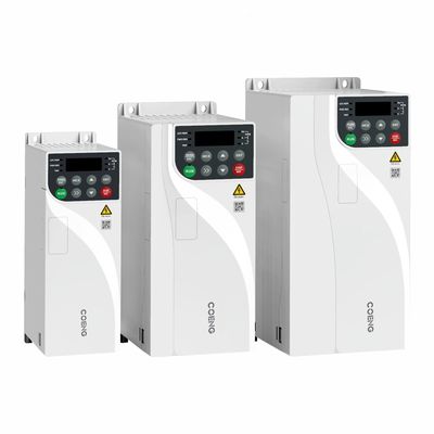
The HV350 Series inverter is a newly developed general-purpose vector inverter. It adopts advanced open-loop and closed-loop vector control technology, supporting asynchronous motor drive control. On the design principles of abundant software functions, better performance and higher reliability, this inverter features smaller volume with improved expandability, more communication functions and easier operation.
General Purpose VFD Vector Frequency Inverter Product Features
High Reliability
Innovative Independent Air Duct
- The innovative design separates the sensitive devices from the air duct, greatly improving the inverter's adaptability to different environments
- The air duct can protect the inverter from dusts and sundries to avoid electrical short circuit, component damage, etc
Advanced Thermal Design Concept and Professional Thermal Simulation Analysis
- Applying efficient and precise thermal simulation software to ensure the thermal reliability of the inverter
- Adopting advanced thermal testing, validation technology and equipment to verify the theoretical results of the thermal design
Rigorous Temperature Rise Testing
- Rigorous full-load and overload testing procedure and strict acceptance criteria for temperature rise of key components supporting long-time reliable operation of the inverter under extreme load condition
- All products passing high-temperature load aging test before ex-work to ensure that all components of the product can work normally
Three-proof Paint Automatic Spraying Process
- Different spraying strategies can be adopted according to the circuit boards, effectively ensuring the uniformity of the circuit board spraying and the consistency of the same batch of the product
High Adaptability
Wide Voltage Range
- Rated voltage: Three-phase 380V ~ 480V
- Input power frequency: (50Hz/60Hz) ±5%
- Allowable voltage fluctuation range: -15%Vac ~ +10%Vac
Low External Interference
- Built-in C3 filter can effectively suppress the high-frequency harmonics generated during the operation of the inverter, meeting the requirements of the EU EN61800-3 standard.
- Simple and user-friendly EMC grounding design effectively reduces ground leakage current.
- System Certification
- European Union CE certification
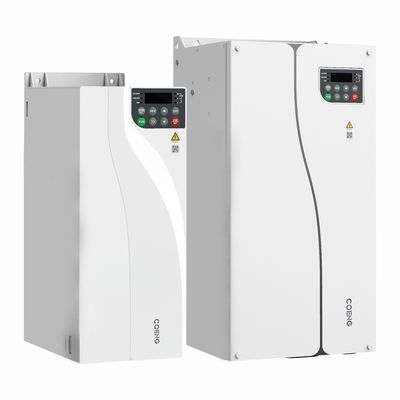
Structural Design
- Book-shaped design with the volume 40% less than traditional models
- Supporting side-by-side installation of multiple inverters
Outstanding Performance
Comprehensive Motor Drive Technology
- Supporting the drive control of three-phase asynchronous motors
- Supporting V/F control, open-loop vector control, and closed-loop vector control
- Supporting speed and torque control
- Supporting speed tracking function, reducing impact current
Accurate Motor Auto-tuning Function
- Supporting accurate auto tuning on motor parameters for convenient operation and debugging, higher control precision and faster response speed
- Comprehensive motor auto-tuning functions, including dynamic, static and static+dynamic auto-tuning
- Comprehensive Motor Control Modes
- V/F Control Mode
- Open-loop Vector Control Mode(OLVC)
- Closed-loop Vector Control Mode(CLVC)
Large Starting Torque
- Open-loop vector control (OLVC): 150% at 0.5Hz
- Closed-loop vector control (CLVC): 200% at 0Hz
High Overload Capacity
- Light overload capacity: 110% of rated light load current for 60 seconds, 150% of rated light load current for 10 seconds
- Heavy overload capacity: 150% of rated heavy load current for 60 seconds, 180% of rated heavy load current for 10 seconds
Diversified Functions
Keypad
- For standard inverters, internal LED keypads are available and external keypads are not supported.
- External LED keyboard can be optionally added.
- Both standard and optional keypads support parameter debugging, operation state monitoring, start/stop control. parameter copying, etc.
Various Expansion Functions
- Optional expansion communication cards support Profibus-DP, Profinet IO, CANopen, Modbus TCP/IP, Ethercat, EtherNet/IP, and other bus
- communications (SLOT1 expansion card slot).
- Optional encoder expansion cards (SLOT2 expansion card slot)
- Optional IO terminal expansion cards (SLOT1 expansion card slot, please refer to "Optional Accessories" for details)
Reliable Braking Function
- The inverter supports DC braking.
- Models of 22kw and below are equipped with a standard built-in braking unit while models of 30kw to 132kw with an optional one.
- Adding a braking resistor enhances braking performance while saving electrical installation space and reducing user electrical costs.
Supporting Various Functions
- Supporting V/F Supporting V/F half separation and complete separation modes
- Supporting process PID control which can be applied in constant temperature control, constant pressure control and tension control
- Supporting position lock to achieve motor zero-speed position locking in CLVC mode
- Supporting wobble function which can be applied in fiber and textile industries
- Supporting random PWM depth to reduce motor noise
- Supporting encoder redundancy operation mode to drive the system to automatically switch to OLVC
- Operation when the encoder is faulty
Supporting Background Software for Quick Debugging
- Supporting such functions as monitoring and parameter editing
- Supporting event logs and fault record
General Purpose VFD Vector Frequency Inverter Product Technical Specification
|
Technical Data |
|||
|
Projects |
Specification Description and Technical Data |
|
|
|
Power input/ |
Input voltage |
Input voltage: 380V (-15%) to 480V (+10%) Phase: Three-phase |
|
|
Input power frequency |
50Hz/60Hz ±5% |
|
|
|
Input voltage imbalance |
≤3% |
|
|
|
Output voltage |
OV-Input voltage |
|
|
|
Output frequency |
0~600Hz |
|
|
|
Motor type |
Asynchronous motor |
|
|
|
Master control performance |
Control mode |
V/F, OLVC(Open-loop Vector Control), CLVC(Closed-loop Vector Control) |
|
|
Speed range |
1:10 V/F; 1:100 OLVC; 1:1000 CLVC |
|
|
|
Starting torque |
OLVC: 150%(0.5Hz), CLVC: 200%(OHz) |
|
|
|
Torque precision |
≤±5%, in Vector control mode |
|
|
|
Torque ripple |
≤±5%, in Vector control mode |
|
|
|
Speed stability |
OLVC, 0.2%; CLVC: 0.1% |
|
|
|
Torque response |
≤5ms, in Vector control mode |
|
|
|
Acceleration/deceleration time |
0.0s~3200.0s; 0.0min~3200.0min |
|
|
|
Torque boost |
0.0%~30.0% |
|
|
|
Overload capacity |
G model: 150% 1min/5min; 180%10s/5min; P model: 110% 1min/5min; 150% 10s/5min |
|
|
|
V/F curve |
Straight-line type, multi-point type, V/F Half separation mode, V/F complete separation mode |
|
|
|
Input frequency resolution |
Digital setting: 0.01Hz, Analog setting: 0.01Hz |
|
|
|
Acceleration/deceleration curve |
Straight line and S-curve |
|
|
|
Main functions |
Simple PLC, Multi-speed control |
16 speed segments supported through control terminals |
|
|
Automatic voltage regulation (AVR) |
Automatically keeps the output voltage constant when grid voltage varies within a certain range |
|
|
|
Fixed length control |
Fixed length control |
|
|
|
Built-in PID |
Easily forms a closed-loop control system |
|
|
|
Multi-motor switching |
Switchover between two groups of motor parameters to control the two motors |
|
|
|
Virtual I/O |
Eight groups of virtual DI/DOenabling simple logic control |
|
|
|
Overvoltage/Overcurrent stall control |
Automatic current and voltage limitation during operation preventing the inverter from tripping due to frequent overcurrent or overvoltage |
|
|
|
Restart after power failure |
After power failure and restoration, the inverter waits for a set time before automatically running |
|
|
|
Quick current limiting |
Avoids frequent overcurrent faults in the inverter |
|
|
|
Frequency setting method |
keypad; terminal UP/DOWN; multi-reference; pulse reference; communication |
|
|
|
Power input/ output |
Analog input terminals |
AI1; AI2: 0V~10V/ 0 (4)mA~20mA |
|
|
Digital input terminals |
DI1-DI5, 5 programmable digital input terminals with opto-isolation, compatible with both |
|
|
|
Digital output terminals |
Open-collector output; output voltage range: 0V~24V; current load capacity: 50mA. |
|
|
|
Analog output terminals |
1-channel 0V ~ 10V/0(4)mA ~ 20mA |
|
|
|
Relay output |
1-channel Form C contact, NO+NC |
|
|
|
Communication |
Communication protocols |
Modbus RTU (standard configuration); Profibus-DP; Profinet IO; CANopen; Modbus TCP/IP; Ethercat; EtherNet/IP (optional configuration) |
|
|
Ambient |
Altitude |
≤1000m: no need for derating |
|
|
Ambient temperature |
-25℃~+40℃ (Running with derating allowed between 40~55) |
|
|
|
Humidity |
15% ~ 95%, No condensation |
|
|
|
Vibration |
3M3, IEC60721-3-3 |
|
|
|
Storage temperature |
−40°C~+70°C |
|
|
|
Installation place |
Indoor, without direct sunlight, free from flammable, corrosive gases, liquids, and conductive |
|
|
|
Optional accessories |
Encoder card, communication expansion card, IO expansion card |
|
|
|
Protections |
Protection against short circuit , overcurrent, overload, overvoltage, undervoltage, phase loss, |
|
|
|
Installation method |
Installed in a cabinet |
|
|
|
Protection rating |
IP20 |
|
|
|
Cooling method |
Air cooling |
|
|
General Purpose VFD Vector Frequency Inverter Product Product Applicantion
Textile, papermaking, object hoisting, plastics, metal products, printing and packaging, building materials, engineering machines and automatic production equipment.
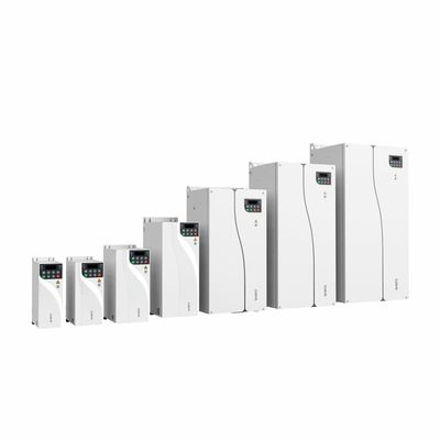
|
HV350 Product Selection Rated voltage: three-phase 380Vac (suitable for operating voltage range of 323V~528V) |
|||||
|
Model |
Heavy Load |
Light Load |
Frame Type |
||
|
Rated Power (kW) |
Rated Output Current |
Rated Power |
Rated Output Current |
||
|
HV350-4T0.75G/1.5PB |
0.75 |
2.5 |
1.5 |
4.2 |
FA |
|
HV350-4T1.5G/2.2PB |
1.5 |
4.2 |
2.2 |
5.8 |
|
|
HV350-4T2.2GB |
2.2 |
5.8 |
- |
- |
|
|
HV350-4T4G/5.5PB |
4 |
9.5 |
5.5 |
13 |
FB |
|
HV350-4T5.5GB |
5.5 |
13 |
- |
- |
|
|
HV350-4T7.5G/11PB |
7.5 |
17 |
11 |
25 |
FC |
|
HV350-4T11GB |
11 |
25 |
- |
- |
|
|
HV350-4T15G/18PB |
15 |
32 |
18.5 |
38 |
FD |
|
HV350-4T18G/22PB |
18.5 |
38 |
22 |
46 |
|
|
HV350-4T22GB |
22 |
46 |
- |
- |
|
|
HV350-4T30G/37P(B) |
30 |
60 |
37 |
75 |
FE |
|
HV350-4T37G/45P(B) |
37 |
75 |
45 |
91 |
|
|
HV350-4T45G/55P(B) |
45 |
91 |
55 |
125 |
|
|
HV350-4T55G/75P(B) |
55 |
125 |
75 |
150 |
FF |
|
HV350-4T75G/90P(B) |
75 |
150 |
90 |
180 |
|
|
HV350-4T90G/110P(B) |
90 |
180 |
110 |
210 |
FG |
|
HV350-4T110G/132P(B) |
110 |
210 |
132 |
250 |
|
![]()
Recommended Products