1. Overview
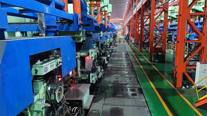
The process of cold rolling production generally includes raw material preparation, straightening, pickling, rolling, degreasing, annealing (heat treatment), finishing and so on. Cold rolling takes hot rolled products as raw materials, and phosphorus should be removed before cold rolling to ensure that the surface of cold rolled products is clean. Rolling is the main process that deforms materials.
As the supplier of the main drive and auxiliary drive frequency converters for the whole line of a large metallurgical rolling enterprise, we fully cooperated with the enterprise to realize the on-time operation and continuous and stable production of the two production lines from product delivery, installation and debugging, production guarantee and technical training.
2. frequency conversion drive scheme
The main and auxiliary drive motors of the 2 section steel production lines are driven by HD2000 series engineering frequency converter, and the automation control system and communication bus of the drive frequency converter adopt the current mainstream ProfiNet technology.
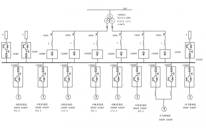
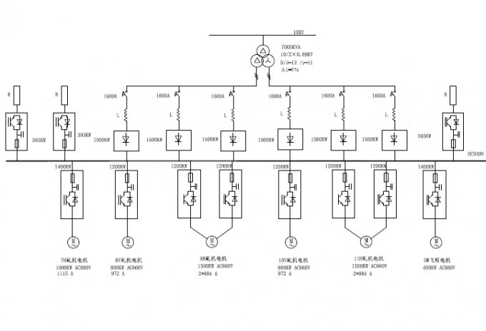
The main drive of the northern line of the project includes 16 1200kW-2000kW main rolling mills and 3 flying shears; the main drive of the southern line includes 19 800kW-1500kW main rolling mills and 3 flying shears, as well as more than 200 sets of frequency conversion cabinets such as straighteners and auxiliary drives, with a total frequency converter capacity of 228MW.
Specifically, the HD2000 series engineering basic rectifier unit (BRU) + brake unit + motor drive unit (MDU) + code disk module is used.
The inverter unit is directly driven by the industry's largest air-cooled 1.2MW and 1.4MW motor drive units, and each motor (or single winding) can meet the drive needs without using multiple units in parallel.
The inverter adopts the cabinet configuration scheme, the input is configured with an input reactor, and the output is not configured with an output reactor.
The single line diagram of the system is as follows (a large number, not all listed) :